|

|
|
| Home | Live Data | Instruments | CHRNS | Proposals |

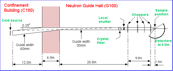
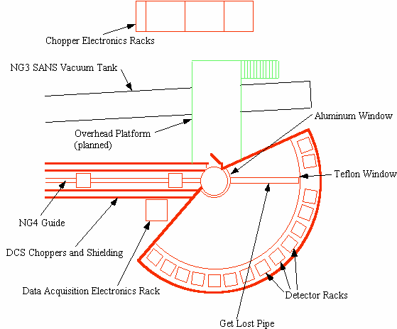
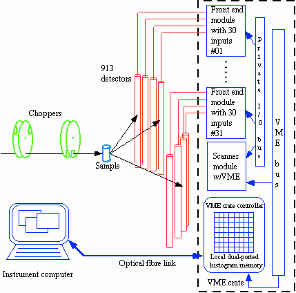
The NG4 neutron guide incorporates an "optical filter" which removes almost all of the high energy neutrons and gamma-rays in the initial section of the guide. After an auxiliary cooled graphite filter and local shutter there are seven disk choppers that collectively produce clean monochromatic bursts of neutrons at the sample position. The sample is located in a large sample chamber, accessible from above and from the side; a radial collimator reduces scattering from the sample environment. The flight chamber is filled with argon gas at atmospheric pressure to reduce the possibility of gas scattering. Each of the 15 detector racks holds three rows of 3He detectors and amplifier-discriminators. The data acquisition system timestamps each neutron event, attaches the detector number, and histograms the information in up to 1024 time channels.
The NG4 neutron guide within the confinement building is 60 mm wide and 150 mm high. Approximately 12 m from the start of the guide, at B, an asymmetric taper is introduced as shown in the attached figure, such that after a further ~6.9 m, at C, the guide width is reduced to 30 mm. Thereafter the guide has parallel sides once again, but its direction has been rotated through ~0.25°. All points beyond point D, which is ~25.3 m from C, are such that there is no line of sight to the guide entrance. The guide ends at E, ~26.0 m downstream from C.

The top and bottom surfaces of the guide are coated with a supermirror coating that has twice the critical angle of natural nickel at any given wavelength. The side surfaces are coated with a multilayer coating such that the critical angle for total reflection is about 1.2 times that of natural nickel at any given wavelength.
The idea of the optical filter is that since there is no line of sight to the source from the end of the guide neutrons and gamma rays cannot reach the end of the guide unless they have been reflected or scattered.
Notwithstanding theory, which says that no neutron with wavelength less than ~ 0.6 Å can be transmitted from the cold source to the end of the guide (point E above) by specular reflection, slightly shorter wavelength neutrons have been observed, and we now understand why; see publication 5(d). To remove these neutrons we have installed a liquid nitrogen cooled pyrolytic graphite filter made of eleven 40 mm wide by 110 mm high "filter grade" ("ZYH") blocks, stacked with their short dimension parallel to the beam. The total length of the filter is 100 mm.
We have installed a cooled graphite filter in the white beam, roughly 0.5 m upstream from the local shutter. This permits measurements at wavelengths down to about 2.3 Angstroms but measurements at wavelengths near 3.335 and 6.67 Angstroms will not be possible.
The DCS uses a set of seven chopper disks and a partitioned guide to produce pulses of neutrons of a single wavelength at the sample position. There are three slots in each of the disks belonging to the first and last counter-rotating chopper pairs. By appropriately phasing these disks the resolution of the instrument can be changed, without having to change the incident wavelength or the speed of the choppers.

|
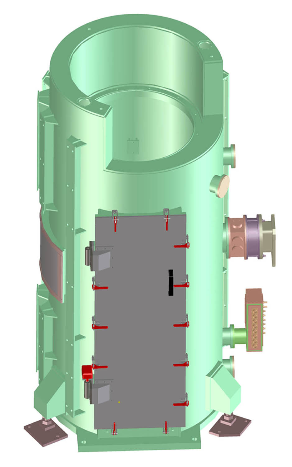
The sample chamber is a double-walled aluminum vessel. It is accessible
from above and from the side through a large gas-tight shielded door.
A cover plate can be installed to seal the top opening.
The chamber can be purged with a breathable gas (80% Ar, 20% O2).
The sample table has 3 translation stages and 3 rotation stages.
In its home position the sample table is 170 mm below the beam center line. A radial collimator is separately installed. Its inside and outside radii are 200 mm and 300 mm. Its inside height is 250 mm. It has 84 Gd2O3-painted blades at 2° intervals. |
Most of this section has yet to be written.
A new window, separating the argon-filled flight chamber from the detectors, has recently been installed. It is a very thin (0.00035", i.e. ~9 micron) 1100 aluminum foil. The window between the sample chamber and the flight chamber has also been changed, from a 3 mm 6061 Al alloy plate to a 0.076 mm (0.003") 1100 Al foil.

This section is yet to be written.
This section is yet to be written.

Go to top
Go to the DCS home page.
Scientific Opportunities | Design Features | Intensity, resolution and Q range
Proposals, Beam Time Requests | Access to the NCNR Facilities | Monetary Assistance Programs
Publications
Source Schedule | Instrument Schedule
Users' guide | Sample Environments | DAVE (Data Analysis Software)
The DCS Instrument Poster | Talks about the DCS | Instrument Details
Go to the NCNR home page.
Go to the NCNR Sample Environments page.
Go to the NCNR Cold Neutron Instruments page.
Go to the NCNR Thermal Neutron Instruments page.
Last modified 11-March-2004 by website owner: NCNR (attn: )